
INVENT experiences increased orders and broadens their portfolio in the global market
For INVENT Umwelt- und Verfahrenstechnik AG, 2023 continued to grow in all areas. The company, which is dedicated to the development and application of high-performance technologies for water and wastewater treatment, received greater than 10% more orders for a fourth year in a row. Growth in the USA with the addition of several reference projects made a significant contribution to this. The launch of a joint venture in India and the opening of an additional production site in Dechsendorf, Bavaria, demonstrate INVENT’s increasing success and more is planned for 2024. INVENT will announce plans for further site and personnel expansions including the expansion of its portfolio of innovative products, which will be presented at this year’s IFAT booth.
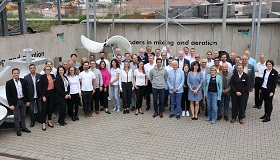
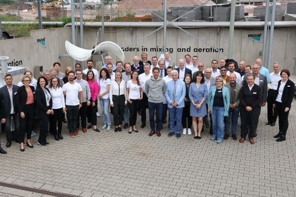
“For us, the past year was characterized by growth and further development,” says Dr.-Ing. Marcus Höfken, CEO of INVENT Umwelt- und Verfahrenstechnik AG. The Erlangen-based company, which specializes in the development of technologies for municipal and industrial water and wastewater treatment, was able to meet and in some cases even exceed the targets it set for 2023 in all areas. “The enormous increase in orders achieved by the Group last year is particularly noteworthy,” says Höfken. For the first time, incoming orders exceeded 40 million euros. This represents a significant increase of more than 10% compared to the previous year. “We have now achieved this growth rate for the fourth year in a row,” Höfken continues. “We are very proud that we can register such rapid and continuous progress in our area and are doing our best to maintain this in the future.”
Growth on the global market
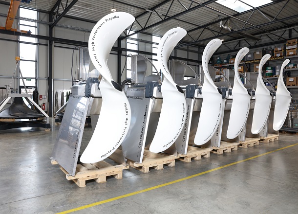
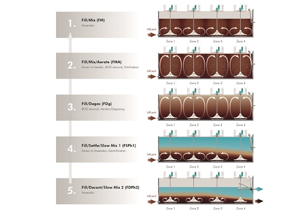
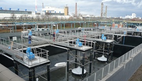
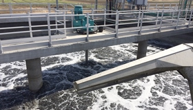
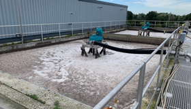
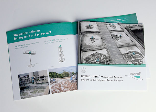
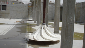
The success of year 2023 was, among other things, can be attributed to strong business in the USA. “With the HYPERCLASSIC®-Mixer and the HYPERCLASSIC®-Mixing and Aeration System as well as our aeration systems, we have equipped water and wastewater treatment plants across all states,” says Höfken. Included was a large municipal wastewater treatment plant in Salt Lake City, Utah. INVENT has also successfully established itself in the field of precipitation and flocculation in the USA. One large installation is a drinking water plant in Houston, Texas, with 48 HYPERCLASSIC®-Mixers. “We are particularly proud of a reference project in Meadville, Pennsylvania,” adds Höfken. “Here, we are equipping a large wastewater treatment plant with our iSBR®-System.”
“We are constantly monitoring the global market and are always on the lookout for new projects and partners with whom we can cooperate,” says Höfken. “We are therefore all the more pleased that we were able to launch our collaboration with the JASH Group in India last year.” The joint venture with the equipment manufacturer aims to offer high-quality, advanced and competitive solutions and services for the Indian market. By working with local manufacturing and service capabilities, INVENT and JASH can provide system solutions that meet the unique challenges of the Indian market. “The joint venture is a testament to the commitment of both our companies to quality, innovation and customer satisfaction,” explains Höfken. “It shows that we have a shared vision for a future where access to clean water is supported by cutting-edge technology and outstanding service.”
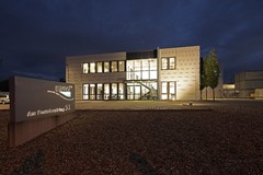
In addition to expanding its international presence, INVENT has also strengthened its national position. “We decided to rent additional space near our Erlangen headquarters in Dechsendorf to provide even more room for production,” explains Höfken. Production of the iFILT®-Diamond Filter has now been completely relocated to the new space, meaning that all production can now take place at one location.
Outlook for 2024 – growth course to be continued
“2023 was a very successful year for us, but we don’t want to rest on our laurels for the future,” Höfken continues. The company has already planned concrete steps and measures for further growth in all areas for 2024. For example, new locations in the USA and other countries are to be developed in the future. “We are in the process of setting up another production site in South Carolina in order to further expand our presence in the USA,” explains Höfken. A subsidiary has also been founded in Argentina in order to further develop the South American market. The company is looking to expand its workforce: “The faster we grow, the more motivated and capable specialists we need who are keen to work on exciting projects and product developments in order to contribute to the promising development of our company,” adds Höfken.
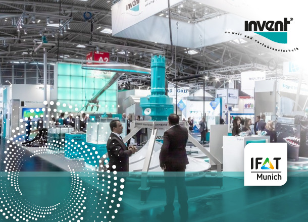
Customers, interested parties and applicants will have the opportunity to find out first-hand about the current status of completed and current projects and get to know the company better in May: INVENT will be present at booth no. 327/426 in hall A2 at IFAT 2024 from May 13 to 17, 2024. The INVENT sales team will be happy to answer questions and exchange ideas on site.


